S5720-12TP-LI-AC
Version Mapping
Table 1 lists the mapping between the S5720-12TP-LI-AC chassis and software versions.
Appearance and Structure
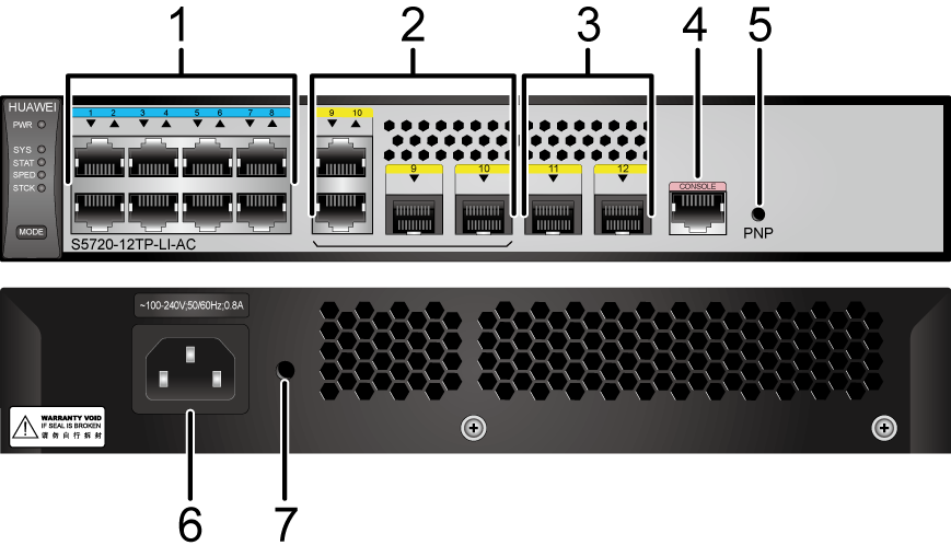
1 |
Eight 10/100/1000BASE-T ports |
2 |
Two combo ports (10/100/1000BASE-T + 100/1000BASE-X) Modules applicable to combo optical ports:
|
3 |
Two 1000BASE-X ports Applicable modules:
NOTE:
If a port uses a GPON optical module, other 1000BASE-X optical ports cannot be used. |
4 |
One console port |
5 |
One PNP button NOTICE:
Applicable in V200R012C00 and later versions: To restore the factory settings and reset the switch, hold down the button for at least 6 seconds. To reset the switch, press the button. Resetting the switch will cause service interruption. Exercise caution when you press the PNP button. |
6 |
AC socket NOTE:
It is used with an AC power cable. |
7 |
Jack for AC power cable locking strap NOTE:
The AC power cable locking strap is not delivered
with the switch. |
- |
- |
Port Description
10/100/1000BASE-T port
Combo port

By default, a combo port works in auto mode, in which the port type is determined as follows:
- If the optical port has no optical module installed and the electrical port has no Ethernet cable connected, the port type depends on which port is connected first. If the electrical port is connected by an Ethernet cable first, the electrical port is used for data switching. If the optical port has an optical module installed first, the optical port is used for data switching.
- If the electrical port has an Ethernet cable connected and is in Up state, the electrical port is still used for data switching when the optical port has an optical module installed.
- If the optical port, no matter in Up or Down state, has an optical module installed, the optical port is still used for data switching when the electrical port has an Ethernet cable connected.
- If the optical port has an optical module installed and the electrical port has an Ethernet cable connected, the optical port is used for data switching after the switch restarts.
1000BASE-X port
Console port
Indicator Description
- If the switch has no configuration file, the system attempts to enter the web initial login mode. In this mode, the status of mode indicators is as follows:
- If the system enters the web initial login mode successfully, all mode indicators turn green and stay on for a maximum of 10 minutes.
- If the system fails to enter the initial login mode, all mode indicators fast blink for 10 seconds and then restore the default status.
- If the switch has a configuration file, the system cannot enter the web initial login mode. In this case, all mode indicators fast blink for 10s, and then return to the default states.
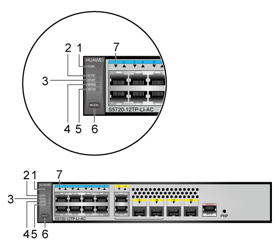
No. |
Indicator |
Name |
Color |
Status |
Description |
|---|---|---|---|---|---|
1 |
PWR |
Power module indicator |
- |
Off |
The switch is powered off. |
Green |
Steady on |
The system power supply is normal. |
|||
2 |
SYS |
System status indicator |
- |
Off |
The system is not running. |
Green |
Fast blinking |
The system is starting. |
|||
Green |
Slow blinking |
The system is running normally. |
|||
Red |
Steady on |
The system does not work normally after registration, or a temperature alarm has been generated. |
|||
3 |
STAT |
Status indicator |
- |
Off |
The status mode is not selected. |
Green |
Steady on |
The status mode (default mode) is selected. If the status mode is selected, the service port indicator shows the port link or activity state. |
|||
4 |
SPED |
Speed indicator |
- |
Off |
The speed mode is not selected. |
Green |
Steady on |
The service port indicators show the port speeds. After 45 seconds, the service port indicators automatically restore to the status mode. |
|||
5 |
STCK |
Stack indicator |
- |
Off |
|
Green |
Steady on |
The switch is a standby or slave switch in a stack, and the service port indicators show the stack ID of the switch. |
|||
Green |
Blinking |
After 45 seconds, the service port indicators automatically restore to the status mode. |
|||
6 |
MODE |
Mode switch button |
- |
- |
If you do not press the MODE button within 45 seconds, the service port indicators restore to the default mode. In this case, the STAT indicator is steady green, the SPED indicator is off, and the STCK indicator is off or blinking green. |
7 |
- |
Service port indicator |
Meanings of service port indicators vary in different modes. For details, see Table 6. |
||
Display Mode |
Color |
Description |
|---|---|---|
Status |
Green |
|
Speed |
Green |
|
Stack |
Green |
Off: Port indicators do not show the stack ID of the switch. If the indicator is steady on, the switch is not a master switch:
If the indicator is blinking, the switch is a master switch:
|
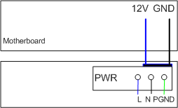
Power Supply Configuration
The S5720-12TP-LI-AC has a built-in power module and does not support pluggable power modules.
Heat Dissipation
The S5720-12TP-LI-AC has no fans and uses natural heat dissipation.
Technical Specifications
Table 7 lists technical specifications of the S5720-12TP-LI-AC.
Item |
Description |
|---|---|
Memory (RAM) |
512 MB |
Flash |
512 MB in total. To view the available flash memory size, run the display version command. |
Mean time between failures (MTBF) |
23.8 years |
Mean time to repair (MTTR) |
2 hours |
Availability |
> 0.99999 |
Service port surge protection |
Common mode: ±7 kV |
Power supply surge protection |
±6 kV in differential mode, ±6 kV in common mode |
Dimensions (H x W x D) |
43.6 mm x 250.0 mm x 180.0 mm (1.72 in. x 9.8 in. x 7.1 in.) |
Weight (with packaging) |
1.8 kg (3.97 lb) |
Stack ports |
Eight 10/100/1000BASE-T ports and two 1000BASE-X ports |
RTC |
Not supported |
RPS |
Not supported |
PoE |
Not supported |
Rated voltage range |
100 V AC to 240 V AC, 50/60 Hz |
Maximum voltage range |
90 V AC to 264 V AC, 47 Hz to 63 Hz |
Maximum power consumption (100% throughput) |
12.85 W |
Typical power consumption (30% of traffic load)
|
10.39 W |
Operating temperature |
0°C to 45°C (32°F to 113°F) at an altitude of 0-1800 m (0-5906 ft.)
NOTE:
When the altitude is 1800-5000 m (5906-16404 ft.), the highest operating temperature reduces by 1°C (1.8°F) every time the altitude increases by 220 m (722 ft.). The operating temperature of the switch is 0°C to 40°C (32°F to 104°F) when it uses GE SFP optical modules with 40 km transmission distance. |
Storage temperature |
-40°C to +70°C (-40°F to +158°F) |
Noise under normal temperature (27°C, sound power) |
Noise-free (no fans) |
Relative humidity |
5% to 95%, noncondensing |
Operating altitude |
0-5000 m (0-16404 ft.) |
Certification |
|
Part number |
98010567 |