S5732-H24UM2CC
Version Mapping
Table 1 lists the mapping between the S5732-H24UM2CC chassis and software versions.
Appearance and Structure
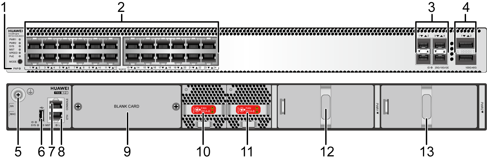
1 |
One PNP button NOTICE:
To restore the factory settings and reset the switch, hold down the button for at least 6 seconds. To reset the switch, press the button. Resetting the switch will cause service interruption. Exercise caution when you press the PNP button. |
2 |
Twenty-four 100M/1000M/2.5GE/5GE/10GE BASE-T PoE++ ports (multi-GE ports) |
3 |
Four 1GE/10GE/25GE SFP28 optical ports Applicable modules and cables:
|
4 |
Two 40GE/100GE QSFP28 optical ports Applicable modules and cables:
|
5 |
Ground screw NOTE:
It is used with a ground cable. |
6 |
One USB port |
7 |
One console port |
8 |
One ETH management port |
9 |
Rear card slot |
10 |
Fan module slot 1 NOTE:
Applicable fan module: FAN-031A-B Fan Module |
11 |
Fan module slot 2 NOTE:
Applicable fan module: FAN-031A-B Fan Module |
12 |
Power module slot 1 NOTE:
Applicable power module: 1000 W AC PoE Power Module (PAC1000S56-CB) |
13 |
Power module slot 2 NOTE:
Applicable power module: 1000 W AC PoE Power Module (PAC1000S56-CB) |
- |
- |
Port Description
100M/1000M/2.5GE/5GE/10GE BASE-T port (multi-GE port)
There are several S5732-H24UM2CC bundles, which consist of different power supplies and ports, as listed in Table 3.
Part Number |
Description |
Remarks |
|---|---|---|
02353HUC |
S5732-H24UM2CC Premium(24*100M/1G/2.5G/5G/10G Ethernet ports, 4*25GE SFP28 + 2*40GE or 2*100GE QSFP28 ports, 1*expansion slot, PoE++, without power module) |
By default, no power supply is configured. By default, multi-GE ports support 100 Mbit/s, 1000 Mbit/s, 2.5 Gbit/s, 5 Gbit/s, and 10 Gbit/s. |
02353SJY |
S5732-H24UM2CC Base(24*100M/1G Ethernet ports, Optional RTU upgrade to 2.5/5/10G, 4*25GE SFP28 + 2*40GE or 2*100GE QSFP28 ports, 1*expansion slot, PoE++, without power module) |
By default, no power supply is configured. By default, multi-GE ports support 100 Mbit/s and 1000 Mbit/s. You can purchase an RTU license to increase the port rate to 2.5 Gbit/s, 5 Gbit/s, or 10 Gbit/s. |
02353SJY-001 |
S5732-H24UM2CC 2.5&10G Bundle(12*100M/1G/2.5G, 12*100M/1G/2.5G/5G/10G Ethernet ports, Optional RTU upgrade to 5/10G, 4*25GE + 2*40GE or 2*100GE, 1*expansion slot, PoE++, 1*1000W AC power) |
By default, one 1000 W AC power module is configured. By default, the first 12 multi-GE ports support 100 Mbit/s, 1000 Mbit/s, and 2.5 Gbit/s. You can purchase an RTU license to increase the port rate to 5 Gbit/s or 10 Gbit/s. By default, the last 12 multi-GE ports support 100 Mbit/s, 1000 Mbit/s, 2.5 Gbit/s, 5 Gbit/s, and 10 Gbit/s. There is a label on the rear side of the device, which contains the default rate "12*2.5GE+12*10GE" supported by the multi-GE ports. |
02353SJY-004 |
S5732-H24UM2CC 10G Bundle(24*100M/1G/2.5G/5G/10G Ethernet ports, 4*25GE SFP28 + 2*40GE or 2*100GE QSFP28 ports, 1*expansion slot, PoE++, 1*1000W AC power) |
By default, one 1000 W AC power module is configured. By default, multi-GE ports support 100 Mbit/s, 1000 Mbit/s, 2.5 Gbit/s, 5 Gbit/s, and 10 Gbit/s. There is a label on the rear side of the device, which contains the default rate "24*10GE" supported by the multi-GE ports. |

A pre-configured or loaded RTU (right to use) license of a device is bound to the device ESN and cannot be unbound or transferred to other devices.
For details about the RTU licenses supported by the device and how to load them, see the License Usage Guide.
A switch with part number 02353SJY-001 is as an example. The switch has a label on its real panel, which shows the default rate of multi-GE ports on the switch.

Cable Type (6-a-1 Bundle) |
Multi-GE Port (Different Rates) |
|||
|---|---|---|---|---|
100M/1000M |
2.5GE |
5GE |
10GE |
|
Category 5e unshielded twisted pair (Cat5e UTP) |
100 m |
100 m |
Not recommended due to high risk |
Not supported |
Category 5e shielded twisted pair (Cat5e STP) |
100 m |
100 m |
100 m |
Not supported |
Category 6 unshielded twisted pair (Cat6 UTP) |
100 m |
100 m |
100 m Not recommended due to high risk |
Not supported |
Category 6 shielded twisted pair (Cat6 STP) |
100 m |
100 m |
100 m |
Not supported |
Category 6A unshielded twisted pair (Cat6A U/UTP) |
100 m |
100 m |
100 m Not recommended due to high risk |
Not supported |
Category 6A foiled/unshielded twisted pair (Cat6A F/UTP) |
100 m |
100 m |
100 m |
100 m |
Category 6A shielded twisted pair (Cat6A STP) |
100 m |
100 m |
100 m |
100 m |
Category 7 twisted pair (Cat7) |
100 m |
100 m |
100 m |
100 m |
6-a-1 stands for the six-around-one cable bundle mode, with one cable in the center and six cables bundled evenly around it.
- 802.3bz requires that the ALSNR value for alien crosstalk between Ethernet cables be greater than 0, but the standards for Cat5e and Cat6 unshielded twisted pairs do not specify the required ALSNR value. Therefore, such cables may not meet the crosstalk requirement in 802.3bz, causing severe problems such as continuous packet loss.
- According the cabling specification TIA TSB-5021, using Cat5e and Cat6 cables for 5G poses high risks.
- Currently, no clear onsite testing or evaluation method is available for checking whether ALSNR of cables conforms to 802.3bz.
If Cat5e and Cat6 unshielded twisted pairs do not meet the 5G requirement, you are advised to replace them with shielded twisted pairs or reduce the rate of ports to 2.5G.
1GE/10GE/25GE SFP28 optical port
A 1GE/10GE/25GE SFP28 optical port sends and receives service data at 1 Gbit/s, 10 Gbit/s, or 25 Gbit/s. Table 5 describes the attributes of a 1GE/10GE/25GE SFP28 optical port.
Attribute |
Description |
|---|---|
Connector Type |
LC/PC |
Optical port attributes |
Depending on the optical module or cable in use |
Standards compliance |
IEEE802.3z, IEEE802.3ae, and IEEE802.3by |
Working mode |
|
40GE/100GE QSFP28 optical port
Console port
ETH management port
USB port
USB flash drives from different vendors differ in model compatibility and drivers. If a USB flash drive cannot be used, try to replace it with another one from a mainstream vendor. Switches support a maximum of 128 GB USB flash drives.
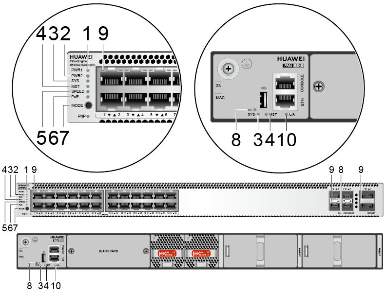
Indicator Description
- If the switch has no configuration file, the system attempts to enter the web initial login mode. In this mode, the status of mode indicators is as follows:
- If the system enters the web initial login mode successfully, all mode indicators turn green and stay on for a maximum of 10 minutes.
- If the system fails to enter the initial login mode, all mode indicators fast blink for 10 seconds and then restore the default status.
- If the switch has a configuration file, the system cannot enter the web initial login mode. In this case, all mode indicators fast blink for 10s, and then return to the default states.
No. |
Indicator |
Name |
Color |
Status |
Description |
|---|---|---|---|---|---|
1 |
PWR1 |
Power module indicator |
- |
Off |
No power module is available in power module slot 1, or the switch has only one power module but the power module does not work normally. |
Green |
Steady on |
A power module is installed in power module slot 1 and is working normally. |
|||
Yellow |
Steady on |
The switch has two power modules installed. Any of the following situations occurs in power module slot 1:
|
|||
2 |
PWR2 |
Power module indicator |
- |
Off |
No power module is available in power module slot 2, or the switch has only one power module but the power module does not work normally. |
Green |
Steady on |
A power module is installed in power module slot 2 and is working normally. |
|||
Yellow |
Steady on |
The switch has two power modules installed. Any of the following situations occurs in power module slot 2:
|
|||
3 |
SYS |
System status indicator |
- |
Off |
The system is not running. |
Green |
Fast blinking |
The system is starting. |
|||
Green |
Steady on |
During the system startup preparation phase, the SYS indicator is steady green, which lasts for a maximum of 30 seconds. |
|||
Green |
Slow blinking |
The system is running normally. |
|||
Red |
Steady on |
The system does not work normally after registration, or a fan alarm or a temperature alarm has been generated. |
|||
4 |
MST |
Stack indicator |
- |
Off |
|
Green |
Steady on |
The stack mode is selected. The switch is a standby or slave switch in a stack, and the service port indicators show the stack ID of the switch. |
|||
Green |
Blinking |
|
|||
5 |
SPEED |
Speed indicator |
- |
Off |
The speed mode is not selected. |
Green |
Steady on |
The speed mode is selected, and service port indicators show the speed of each port. |
|||
6 |
PoE |
PoE indicator |
- |
Off |
The PoE mode is not selected. |
Green |
Steady on |
The PoE mode is selected, and service port indicators show the PoE status of each port. |
|||
7 |
MODE |
Mode switch button |
- |
- |
If you do not press the MODE button within 45 seconds, the service port indicators restore to the default mode. In this case, the SPEED and PoE indicators are off. |
8 |
ID |
ID indicator |
- |
Off |
The ID indicator is not used (default state). |
Blue |
Steady on |
The indicator identifies the switch to maintain. The ID indicator can be turned on or off remotely to help field engineers find the switch to maintain. |
|||
9 |
- |
Service port indicator |
Meanings of service port indicators vary in different modes. For details, see Table 10. |
||
10 |
L/A |
ETH port indicator |
- |
Off |
The ETH port is not connected. |
Green |
Steady on |
The ETH port is connected. |
|||
Green |
Blinking |
The ETH port is sending or receiving data. |
|||
Display Mode |
Color |
Status |
Description |
|---|---|---|---|
Default mode |
- |
Off |
The port is not connected or has been shut down. |
Green |
Steady on |
A link has been established on the port. |
|
Green |
Blinking |
The port is sending or receiving data. |
|
MST stack mode |
- |
Off |
Port indicators do not show the stack ID of the switch. |
Green |
Steady on |
The switch is not the master switch in a stack.
|
|
Green |
Blinking |
The switch is the master switch in a stack.
|
|
Speed mode |
- |
Off |
The port is not connected or has been shut down. |
Green |
Steady on |
|
|
Green |
Blinking |
|
|
PoE mode |
- |
Off |
The port is not providing power to a powered device (PD). |
Green |
Steady on |
The port is providing power to a PD. |
|
Yellow |
Steady on |
The PoE function is disabled on the port. |
|
Yellow |
Blinking |
The port stops providing PoE power because of an exception (for example, an incompatible PD is connected to the port). |
|
Green and yellow |
Blinking green and yellow alternately |
The port fails to supply power to a PD due to one of the following reasons:
|
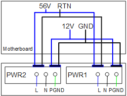
Power Supply Configuration
The S5732-H24UM2CC is a PoE switch. It has two power module slots, each of which can have a 1000 W PoE power module installed. Table 11 lists its power supply configurations.
Power Module 1 |
Power Module 2 |
Available PoE Power |
Maximum Number of Ports (Fully Loaded) |
|---|---|---|---|
1000 W (220 V) |
– |
675 W |
|
1000 W (110 V) |
– |
580 W |
|
1000 W (220 V) |
1000 W (220 V) |
1440 W |
|
1000 W (110 V) |
1000 W (110 V) |
1435 W |
|
When a switch has two power modules installed, the two power modules work in redundancy mode to provide power for the chassis and in load balancing mode to provide power for PDs.
Heat Dissipation
The S5732-H24UM2CC uses pluggable fan modules for forced air cooling. Air flows in from the left, right, and front sides, and exhausts from the rear panel.

Technical Specifications
Table 12 lists technical specifications of the S5732-H24UM2CC.
Item |
Description |
|---|---|
Memory (RAM) |
4 GB |
Flash |
2 GB in total. To view the available flash memory size, run the display version command. |
Mean time between failures (MTBF) |
38.05 years |
Mean time to repair (MTTR) |
2 hours |
Availability |
> 0.99999 |
Service port surge protection |
Common mode: ±6 kV |
Power supply surge protection |
±6 kV in differential mode, ±6 kV in common mode |
Dimensions (H x W x D) |
|
Weight (including package) |
8 kg (17.64 lb) |
Stack ports |
Any Ethernet electrical port (10GE) or optical port (10GE/25GE/40GE/100GE) |
RTC |
Supported |
RPS |
Not supported |
PoE |
Supported |
Rated voltage range |
|
Maximum voltage range |
|
Maximum power consumption (100% throughput, full speed of fans) |
|
Typical power consumption (30% of traffic load, tested according to ATIS standard) |
161 W (without card) |
Operating temperature |
-5°C to +45°C (23°F to 113°F) at an altitude of 0-1800 m (0-5906 ft.)
NOTE:
When the altitude is 1800-5000 m (5906-16404 ft.), the highest operating temperature reduces by 1°C (1.8°F) every time the altitude increases by 220 m (722 ft.). The switch cannot be started when the ambient temperature is lower than 0°C (32°F). |
Storage temperature |
-40°C to +70°C (-40°F to +158°F) |
Noise under normal temperature (27°C, sound power) |
< 59.2 dB(A) |
Relative humidity |
5% to 95%, noncondensing |
Operating altitude |
0-5000 m (0-16404 ft.) |
Certification |
|
Part number |
|