S5735-L32ST4X-A
Version Mapping
Table 1 lists the mapping between the S5735-L32ST4X-A chassis and software versions.
Appearance and Structure
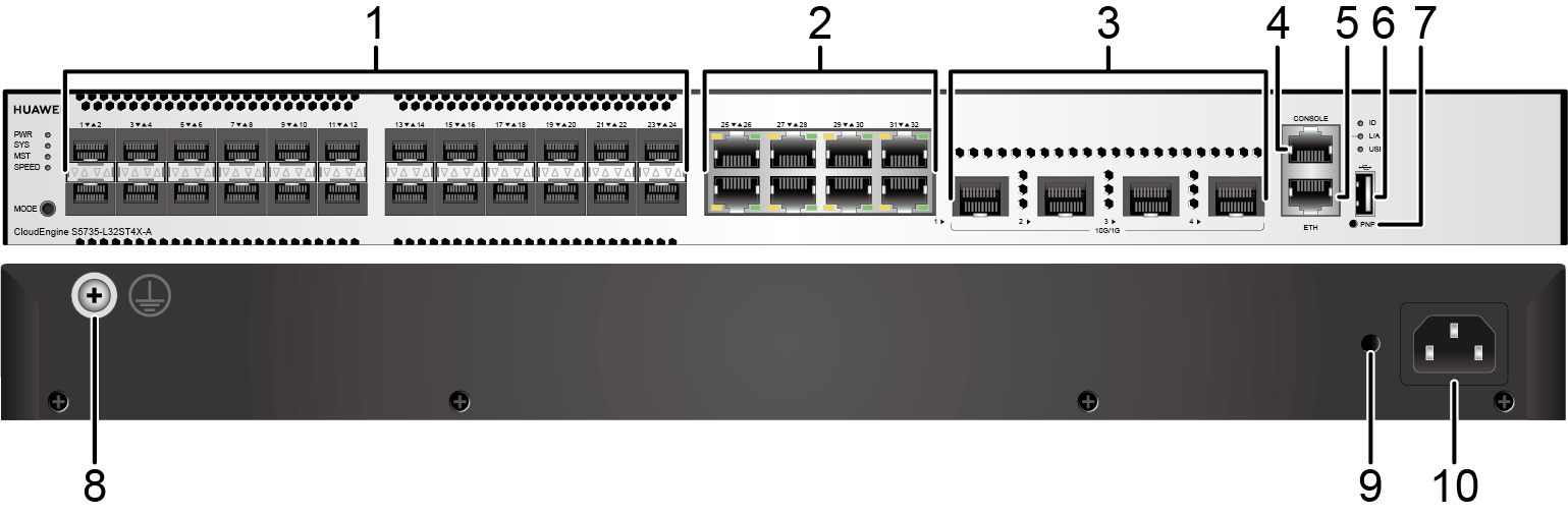
1 |
Twenty-four 100/1000BASE-X ports Applicable modules:
|
2 |
Eight 10/100/1000BASE-T ports |
3 |
Four 10GE SFP+ ports Applicable modules and cables:
|
4 |
One console port |
5 |
One ETH management port |
6 |
One USB port |
7 |
One PNP button NOTICE:
To restore the factory settings and reset the switch, hold down the button for at least 6 seconds. To reset the switch, press the button. Resetting the switch will cause service interruption. Exercise caution when you press the PNP button. |
8 |
Ground screw NOTE:
It is used with a ground cable. |
9 |
Jack for AC power cable locking strap NOTE:
The AC power cable locking strap is not delivered
with the switch. |
10 |
AC socket NOTE:
It is used with an AC power cable. |
Port Description
100/1000BASE-X port
10/100/1000BASE-T port
10GE SFP+ port
Console port
ETH management port
USB port

USB flash drives from different vendors differ in model compatibility and drivers. If a USB flash drive cannot be used, try to replace it with another one from a mainstream vendor. Switches support a maximum of 128 GB USB flash drives.
Indicator Description
- If the switch has no configuration file, the system attempts to enter the web initial login mode. In this mode, the status of mode indicators is as follows:
- If the system enters the web initial login mode successfully, all mode indicators turn green and stay on for a maximum of 10 minutes.
- If the system fails to enter the initial login mode, all mode indicators fast blink for 10 seconds and then restore the default status.
- If the switch has a configuration file, the system cannot enter the web initial login mode. In this case, all mode indicators fast blink for 10s, and then return to the default states.
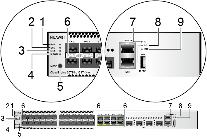
No. |
Indicator |
Name |
Color |
Status |
Description |
|---|---|---|---|---|---|
1 |
PWR |
Power module indicator |
- |
Off |
The switch is powered off. |
Green |
Steady on |
The system power supply is normal. |
|||
2 |
SYS |
System status indicator |
- |
Off |
The system is not running. |
Green |
Fast blinking |
The system is starting. |
|||
Green |
Steady on |
During the system startup preparation phase, the SYS indicator is steady green, which lasts for a maximum of 30 seconds. |
|||
Green |
Slow blinking |
The system is running normally. |
|||
Red |
Steady on |
The system does not work normally after registration, or a fan alarm or a temperature alarm has been generated. |
|||
3 |
MST |
Stack indicator |
- |
Off |
|
Green |
Steady on |
The stack mode is selected. The switch is a standby or slave switch in a stack, and the service port indicators show the stack ID of the switch. |
|||
Green |
Blinking |
|
|||
4 |
SPEED |
Speed indicator |
- |
Off |
The speed mode is not selected. |
Green |
Steady on |
The speed mode is selected, and service port indicators show the speed of each port. |
|||
5 |
MODE |
Mode switch button |
- |
- |
If you do not press the MODE button within 45 seconds, the service port indicators restore to the default mode. In this case, the SPEED indicators are off. |
6 |
- |
Service port indicator |
Meanings of service port indicators vary in different modes. For details, see Table 8. |
||
7 |
ID |
ID indicator |
- |
Off |
The ID indicator is not used (default state). |
Blue |
Steady on |
The indicator identifies the switch to maintain. The ID indicator can be turned on or off remotely to help field engineers find the switch to maintain. |
|||
8 |
L/A |
ETH port indicator |
- |
Off |
The ETH port is not connected. |
Green |
Steady on |
The ETH port is connected. |
|||
Green |
Blinking |
The ETH port is sending or receiving data. |
|||
9 |
USB |
USB-based deployment indicator |
- |
Off |
|
Green |
Steady on |
A USB-based deployment has been completed. |
|||
Green |
Blinking |
The system is reading data from a USB flash drive. |
|||
Yellow |
Steady on |
The switch has copied all the required files and completed the file check. The USB flash drive can be removed from the switch. |
|||
Red |
Blinking |
An error has occurred when the system is executing the configuration file or reading data from the USB flash drive. |
|||
Display Mode |
Color |
Status |
Description |
|---|---|---|---|
Default mode |
- |
Off |
The port is not connected or has been shut down. |
Green |
Steady on |
A link has been established on the port. |
|
Green |
Blinking |
The port is sending or receiving data. |
|
MST stack mode |
- |
Off |
Port indicators do not show the stack ID of the switch. |
Green and yellow |
Steady on |
The switch is not the master switch in a stack.
|
|
Green and yellow |
Blinking |
The switch is the master switch in a stack.
|
|
Speed mode |
- |
Off |
The port is not connected or has been shut down. |
Green and yellow |
Steady on |
10M/100M/1000M port: The port is operating at 10 Mbit/s or 100 Mbit/s. 1000M/10GE port: The port is operating at 1000 Mbit/s. |
|
Green and yellow |
Blinking |
10M/100M/1000M port: The port is operating at 1000 Mbit/s. 1000M/10GE port: The port is operating at 10 Gbit/s. |
Power Supply Configuration
The S5735-L32ST4X-A has a built-in AC power module and does not support pluggable power modules.
Heat Dissipation
The S5735-L32ST4X-A has two built-in fans for forced air cooling. Air flows in from the left side and front panel, and exhausts from the right side.

Technical Specifications
Table 9 lists technical specifications of the S5735-L32ST4X-A.
Item |
Description |
|---|---|
Memory (RAM) |
1 GB |
Flash |
512 MB in total. To view the available flash memory size, run the display version command. |
Mean time between failures (MTBF) |
85.87 years |
Mean time to repair (MTTR) |
2 hours |
Availability |
> 0.99999 |
Service port surge protection |
Common mode: ±7 kV |
Power supply surge protection |
±6 kV in differential mode, ±6 kV in common mode |
Dimensions (H x W x D) |
|
Weight (with packaging) |
4.31 kg (9.5 lb) |
Stack ports |
Any 10/100/1000BASE-T ports, 100/1000BASE-X ports, or 10GE SFP+ ports (applicable in V200R019C10 and later versions) |
RTC |
Not supported |
RPS |
Not supported |
PoE |
Not supported |
Rated voltage range |
|
Maximum voltage range |
|
Maximum power consumption (100% throughput, full speed of fans) |
65 W |
Typical power consumption (30% of traffic load)
|
46 W |
Operating temperature |
-5°C to +50°C (23°F to 122°F) at an altitude of 0-1800 m (0-5906 ft.)
NOTE:
When the altitude is 1800-5000 m (5906-16404 ft.), the highest operating temperature reduces by 1°C (1.8°F) every time the altitude increases by 220 m (722 ft.). The switch cannot be started when the ambient temperature is lower than 0°C (32°F). |
Short-term operating temperature |
-5°C to +55°C (23°F to 131°F) at an altitude of 0-1800 m (0-5906 ft.) NOTE:
When the altitude is 1800-5000 m (5906-16404 ft.), the highest operating temperature reduces by 1°C (1.8°F) every time the altitude increases by 220 m (722 ft.). The equipment can operate beyond the normal operating
temperature range for a short-term period, but the following conditions
must be met:
The equipment cannot start when the temperature is lower than 0°C (32°F). The maximum distance of optical modules used in these conditions cannot exceed 10 km. |
Storage temperature |
-40°C to +70°C (-40°F to +158°F) |
Noise under normal temperature (27°C, sound power) |
< 53.3 dB(A) |
Relative humidity |
5% to 95%, noncondensing |
Operating altitude |
0-5000 m (0-16404 ft.) |
Certification |
|
Part number |
98010929 |