Understanding VBST
VBST is equivalent to running STP or RSTP in each VLAN so that spanning trees in different VLANs are independent of each other. Though VBST does not provide multi-instance, VBST implements load balancing of traffic from different VLANs.
- One root bridge
- Two measurements: ID and path cost
- Three port statuses: Discarding, Learning, and Forwarding
- Five port roles: root port, alternate port, backup port, designated port, and edge port
- Three timers: Hello Time, Forward Delay, and Max Age
-
In VBST, the BID consists of the bridge priority, VLAN ID, and bridge MAC address. The sum of the bridge priority and VLAN ID occupies the leftmost 16 bits, and the bridge MAC address occupies the rightmost 48 bits.
On a VBST network, the device with the smallest bridge ID will be selected as the root bridge.
VBST transmits VBST BPDUs in VLANs to determine the network topology. VBST BPDUs are based on STP/RSTP BPDUs and a 4-byte 802.1Q tag is added between the source MAC address and protocol length. Figure 1 shows the comparisons between the STP/RSTP BPDU and VBST BPDU.
The DMAC identifies the destination MAC address of packets. The DMAC in a VBST BPDU is 0100-0CCC-CCCD; the Data field in a standard RSTP/STP BPDU is used as the Data field in a VBST BPDU. By default, the Data field in a standard RSTP BPDU is used as the Data field in a VBST BPDU.
VBST implements VLAN-based spanning tree calculation, topology convergence, and interworking with spanning tree protocols of other vendors.

VBST Topology Calculation
VBST supports VLAN-based topology calculation. Tagged VBST BPDUs are sent in each VLAN except VLAN 1 and topology calculation is performed separately. The VBST topology calculation method is similar to the STP/RSTP calculation method. For details, see STP Topology Calculation. Different root bridges can be selected in VLANs. Figure 2 shows the topology calculation results of STP/RSTP and VBST.
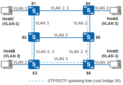
Through topology calculation, STP/RSTP generates a spanning tree with the root bridge as S6. The links between S2 and S5 and between S1 and S4 are blocked. HostA and HostB belong to VLAN 2. The link between S2 and S5 does not permit packets of VLAN 2 to pass through because the link between S2 and S5 is blocked. Therefore, HostA fails to communicate with HostB.
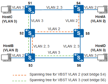
Through topology calculation, VBST generates spanning trees VLAN 2 and VLAN 3 with root bridges as S4 and S6 respectively. Traffic in VLAN 2 and VLAN3 is forwarded through their respective spanning trees so that traffic is load balanced between paths S2-S5 and S3-S6.
VBST BPDU Forwarding
- When trunk or hybrid ports are configured on the local and remote devices, the devices send RST BPDUs and VBST BPDUs encapsulated with RSTP data in the default VLAN — VLAN 1, to each other. At the same time, they send VBST BPDUs encapsulated with RSTP data in other VLANs to which their ports are added. The two devices can identify the BPDUs carrying VLAN information, so a VLAN-based spanning tree is formed.
- When access or QinQ ports are configured on the local and remote devices, the local and remote devices send RST BPDUs to each other in the VLANs to which their ports are added. Topology calculation is performed as defined by RSTP. Because RSTP does not differentiate VLANs, a spanning tree shared by VLANs is formed.
Fast Convergence of VBST
Common mode
The Proposal/Agreement mechanism in common mode supported by VBST is similar to that supported by RSTP. For details, see How RSTP Achieves Rapid Convergence.
Enhanced mode
The Proposal/Agreement mechanism in enhanced mode supported by VBST is similar to that supported by MSTP. For details, see MSTP Fast Convergence.
Protection Mechanisms of VBST
Similar to RSTP, VBST provides BPDU protection, TC protection, root protection, and loop protection. For details, see Protection functions.
Interworking Between VBST and PVST/PVST+/Rapid PVST+
On a live network, a VBST-enabled device may connect to a device enabled with PVST/PVST+/Rapid PVST+.
Trunk interface
When a VBST-enabled device connects to a device enabled with Rapid PVST+, the VBST-enabled device sends standard RSTP BPDUs (or VBST BPDUs with the Data field of RSTP BPDUs) and VBST BPDUs with the Data field of RSTP BPDUs in other VLANs to exchange with the device enabled with Rapid PVST+.
When a VBST-enabled device connects to a device enabled with PVST+, the VBST-enabled device sends standard STP BPDUs (or VBST BPDUs with the Data field of STP BPDUs) and VBST BPDUs with the Data field of STP BPDUs in other VLANs to exchange with the device enabled with PVST+.
When a VBST-enabled device connects to a PVST-enabled device, packet exchange is similar to that in the scenario where a VBST-enabled device connects to a device enabled with PVST+. The difference is that the VBST-enabled device and PVST-enabled device send only VBST BPDUs with the Data field of STP BPDUs in VLAN 1.
The two devices can identify the BPDUs carrying VLAN information, so a VLAN-based spanning tree is formed. The connection between a VBST-enabled device and a device enabled with PVST/PVST+/Rapid PVST+ through a trunk interface is similar to the connection between two VBST-enabled devices.
Access interface
A VBST-enabled device uses standard STP BPDUs to exchange with the device enabled with PVST/PVST+ or RSTP BPDUs to exchange with the device enabled with Rapid PVST+ according to the VLAN that the access interface belongs to. Topology calculation is performed as defined by STP/RSTP. Because STP/RSTP does not differentiate VLANs, a spanning tree shared by VLANs is formed.