PIM (*, G) Join/Prune
Multicast receivers join/leave a multicast group in PIM (*, G) mode.
Table 1 lists the implementation modes of PIM (*, G) multicast joining and leaving.
Implementation Mode |
Principle |
Advantage |
Disadvantage |
|---|---|---|---|
PIM (*, G) multicast joining and leaving across the public network |
The private network rendezvous point (RP) can be deployed on either a CE or a PE. |
|
|
PIM (*, G) multicast joining and leaving not across the public network |
PIM (*, G) entries are converted to PIM (S, G) entries before being transmitted to remote PEs across the public network. |
|
The private network RP can be deployed on either a PE or a CE. If a CE serves as the private network RP, the CE must establish an MSDP peer relationship with the corresponding PE. |
PIM (*, G) Multicast Joining and Leaving Across the Public Network
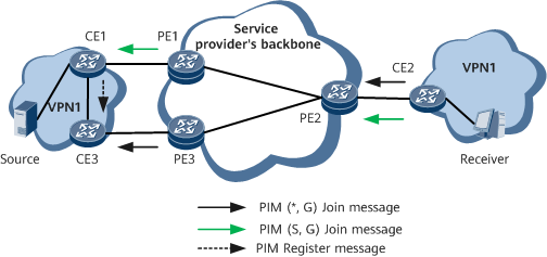
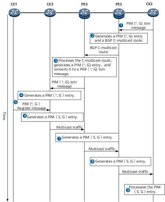
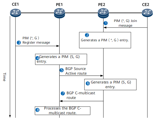
On the network shown in Figure 1, CE3 serves as the RP. Figure 2 shows the time sequence for establishing an RPT. Table 2 describes the procedure for establishing an RPT.
Step |
Device |
Key Action |
|---|---|---|
|
CE2 |
After receiving a user join request through IGMP, CE2 sends a PIM (*, G) Join message to PE2. |
|
PE2 |
After receiving the PIM (*, G) Join message, PE2 generates a PIM (*, G) entry, in which the downstream interface is the interface that receives the PIM (*, G) Join message. PE2 searches for the unicast route to the RP and finds that the upstream device is PE3. PE2 then generates a BGP C-multicast route (Shared Tree Join route) and sends it to PE3 through the BGP peer connection. NOTE:
For details about BGP C-multicast routes, see MVPN NLRI. |
|
PE3 |
After PE3 receives the BGP C-multicast route (Shared Tree Join route):
|
|
CE3 |
Upon receipt of the PIM (*, G) Join message, CE3 generates a PIM (*, G) entry. In this entry, the downstream interface is the interface that receives the PIM (*, G) Join message. Then, an RPT rooted at CE3 and with CE2 as the leaf node is established. |
|
CE1 |
After CE1 receives multicast traffic from the multicast source, CE1 sends a PIM Register message to CE3. |
|
CE3 |
Upon receipt of the PIM Register message, CE3 generates a PIM (S, G) entry, which inherits the outbound interface of the previously generated PIM (*, G) entry. In addition, CE3 sends multicast traffic to PE3. |
|
PE3 |
Upon receipt of the multicast traffic, PE3 generates a PIM (S, G) entry, which inherits the outbound interface of the previously generated PIM (*, G) entry. Because the outbound interface of the PIM (*, G) entry is a P2MP tunnel interface, multicast traffic is imported to the I-PMSI tunnel. |
|
PE2 |
Upon receipt of the multicast traffic, PE2 generates a PIM (S, G) entry, which inherits the outbound interface of the previously generated PIM (*, G) entry. |
|
CE2 |
Upon receipt of the multicast traffic, CE2 sends the multicast traffic to multicast receivers. |


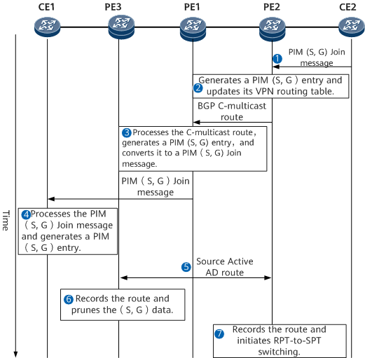
When the multicast traffic sent by the multicast source exceeds the threshold set on set, CE2 initiates RPT-to-SPT switching. Figure 3 shows the time sequence for switching an RPT to an SPT. Table 3 describes the procedure for switching an RPT to an SPT.

When the receiver PE receives multicast traffic transmitted along the RPT, the receiver PE immediately initiates RPT-to-SPT switching. The RPT-to-SPT switching process on the receiver PE is similar to that on CE2.
Step |
Device |
Key Action |
|---|---|---|
|
CE2 |
After the received multicast traffic exceeds the set threshold, CE2 initiates RPT-to-SPT switching by sending a PIM (S, G) Join message to PE2. |
|
PE2 |
Upon receipt of the PIM (S, G) Join message, PE2 updates the outbound interface status in its PIM (S, G) entry, and switches the PIM (S, G) entry to the SPT. Then, PE2 searches its multicast routing table for a route to the multicast source. After PE2 finds that the upstream device on the path to the multicast source is PE1, PE2 sends a BGP C-multicast route (Source Tree Join route) to PE1. |
|
PE1 |
Upon receipt of the BGP C-multicast route (Source Tree Join route), PE1 generates a PIM (S, G) entry, and sends a PIM (S, G) Join message to CE1. |
|
CE1 |
Upon receipt of the PIM (S, G) Join message, CE1 generates a PIM (S, G) entry. Then, the RPT-to-SPT switching is complete, and CE1 can send multicast traffic to PE1. |
|
PE1 |
To prevent duplicate multicast traffic, PE1 carries the PIM (S, G) entry information in a Source Active AD route and sends the route to all its BGP peers. |
|
PE3 |
Upon receipt of the Source Active AD route, PE3 records the route. After RPT-to-SPT switching, PE3, the ingress of the P2MP tunnel for the RPT, deletes received multicast traffic, generates the (S, G, RPT) state, and sends a PIM (S, G, RPT) Prune to its upstream. In addition, PE3 updates its VPN multicast routing entries and stops forwarding multicast traffic. NOTE:
To prevent packet loss during RPT-to-SPT switching, the PIM (S, G, RPT) Prune operation is performed after a short delay. |
|
PE2 |
Upon receipt of the Source Active AD route, PE2 records the route. Because the Source Active AD route carries information about the PIM (S, G) entry for the RPT, PE2 initiates RPT-to-SPT switching. After PE2 sends a BGP C-multicast route (Source Tree Join route) to PE1, PE2 can receive multicast traffic from PE1. |
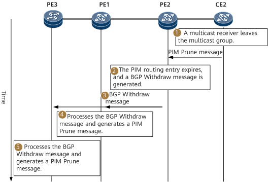
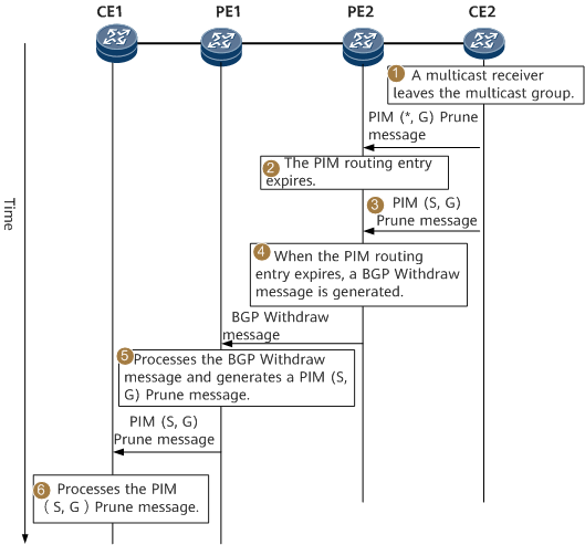
Figure 4 shows the time sequence for leaving a multicast group in PIM (*, G) mode. Table 4 describes the procedure for leaving a multicast group in PIM (*, G) mode.
Step |
Device |
Key Action |
|---|---|---|
|
CE2 |
After CE2 detects that a multicast receiver attached to itself leaves the multicast group, CE2 sends a PIM (*, G) Prune message to PE2. If CE2 has switched to the SPT, CE2 also sends a PIM (S, G) Prune message to PE2. |
|
PE2 |
Upon receipt of the PIM (*, G) Prune message, PE2 deletes the corresponding PIM (*, G) entry. Upon receipt of the PIM (S, G) Prune message, PE2 deletes the corresponding PIM (S, G) entry. |
|
PE2 |
PE2 sends a BGP Withdraw message (Shared Tree Join route) to PE3 and a BGP Withdraw message (Source Tree Join route) to PE1. |
|
PE1 |
Upon receipt of the BGP Withdraw message (Source Tree Join route), PE1 deletes the previously recorded BGP C-multicast route (Source Tree Join route) as well as the outbound interface in the PIM (S, G) entry. |
|
PE3 |
Upon receipt of the BGP Withdraw message (Shared Tree Join route), PE3 deletes the previously recorded BGP C-multicast route (Shared Tree Join route) as well as the outbound interface in the PIM (S, G) entry. |


PIM (*, G) Multicast Joining and Leaving Not Across the Public Network
On the network show in Figure 1, each site of the MVPN is a PIM-SM BSR domain. The PE2 serves as the RP. Figure 5 shows the time sequence for joining a multicast group when a PE serves as the RP. Table 5 describes the procedure for joining a multicast group when a PE serves as the RP.
Step |
Device |
Key Action |
|---|---|---|
|
CE2 |
After receiving a user join request through IGMP, CE2 sends a PIM (*, G) Join message to PE2. |
|
PE2 |
Upon receipt of the PIM (*, G) Join message, PE2 generates a PIM (*, G) entry. Because PE2 is the RP, PE2 does not send the BGP C-multicast route (Shared Tree Join route) to other devices. Then, an RPT rooted at PE2 and with CE2 as the leaf node is established. |
|
CE1 |
After CE1 receives multicast traffic from the multicast server, CE1 sends a PIM Register message to PE1. |
|
PE1 |
Upon receipt of the PIM Register message, PE1 generates a PIM (S, G) entry. |
|
PE1 |
PE1 sends a Source Active AD route to all its BGP peers. |
|
PE2 |
Upon receipt of the Source Active AD route, PE2 generates a PIM (S, G) entry, which inherits the outbound interface of the previously generated PIM (*, G) entry. |
|
PE2 |
PE2 initiates RPT-to-SPT switching and sends a BGP C-multicast route (Source Tree Join route) to PE1. |
|
PE1 |
Upon receipt of the BGP C-multicast route (Source Tree Join route), PE1 imports multicast traffic to the I-PMSI tunnel based on the corresponding VPN multicast forwarding entry. Then, multicast traffic is transmitted over the I-PMSI tunnel to CE2. |
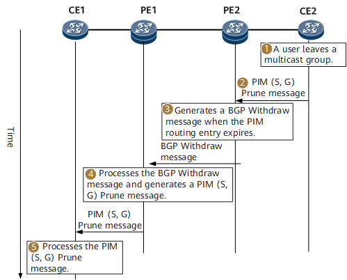
Figure 6 shows the time sequence for leaving a multicast group when a PE serves as the RP. Table 6 describes the procedure for leaving a multicast group when a PE serves as the RP.
Step |
Device |
Key Action |
|---|---|---|
|
CE2 |
After CE2 detects that a multicast receiver attached to itself leaves the multicast group, CE2 sends a PIM (*, G) Prune message to PE2. |
|
PE2 |
Upon receipt of the PIM (*, G) Prune message, PE2 deletes the corresponding PIM (*, G) entry. |
|
CE2 |
CE2 sends a PIM (S, G) Prune message to PE2. |
|
PE2 |
Upon receipt of the PIM (S, G) Prune message, PE2 deletes the corresponding PIM (S, G) entry. PE2 sends a BGP Withdraw message (Source Tree Join route) to PE1. |
|
PE1 |
Upon receipt of the BGP Withdraw message (Source Tree Join route), PE1 deletes the previously recorded BGP C-multicast route (Source Tree Join route) as well as the outbound interface in the PIM (S, G) entry. In addition, PE1 sends a PIM (S, G) Prune message to CE1. |
|
CE1 |
Upon receipt of the PIM (S, G) Prune message, CE1 stops sending multicast traffic to CE2. |

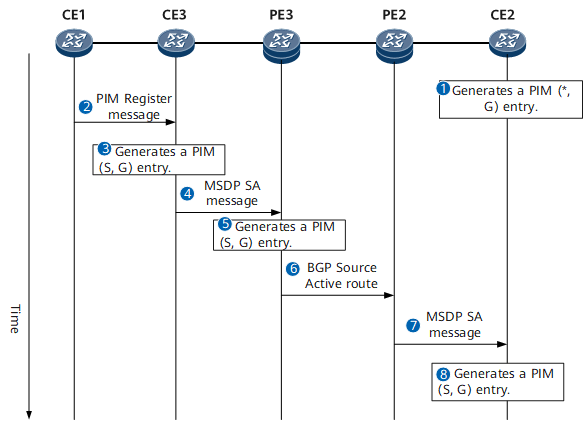
On the network show in Figure 1, each site of the MVPN is a PIM-SM BSR domain. The CE2 serves as the RP. CE3 has established an MSDP peer relationship with PE3, and PE2 has established an MSDP peer relationship with CE2. Figure 7 shows the time sequence for joining a multicast group when a CE serves as the RP. Table 7 describes the procedure for joining a multicast group when a CE serves as the RP.
Step |
Device |
Key Action |
|---|---|---|
|
CE2 |
After receiving a user join request through IGMP, CE2 generates a PIM (*, G) Join message. Because CE2 is the RP, CE2 does not send the PIM (*, G) Join message to its upstream. |
|
CE1 |
After CE1 receives multicast traffic from the multicast server, CE1 sends a PIM Register message to CE3. |
|
CE3 |
Upon receipt of the PIM Register message, CE3 generates a PIM (S, G) entry. |
|
CE3 |
CE3 carries the PIM (S, G) entry information in an MSDP Source Active (SA) message and sends the message to its MSDP peer, PE3. |
|
PE3 |
Upon receipt of the MSDP SA message, PE3 generates a PIM (S, G) entry. |
|
PE3 |
PE3 carries the PIM (S, G) entry information in a Source Active AD route and sends the route to other PEs. |
|
PE2 |
Upon receipt of the Source Active AD route, PE2 learns the PIM (S, G) entry information carried in the route. Then, PE2 sends an MSDP SA message to transmit the PIM (S, G) entry information to its MSDP peer, CE2. |
|
CE2 |
Upon receipt of the MSDP SA message, CE2 learns the PIM (S, G) entry information carried in the message and generates a PIM (S, G) entry. Then, CE2 initiates a PIM (S, G) join request to the multicast source. Finally, CE2 forwards the multicast traffic to multicast receivers. |
Figure 8 shows the time sequence for leaving a multicast group when a CE serves as the RP. Table 8 describes the procedure for leaving a multicast group when a CE serves as the RP.
Step |
Device |
Key Action |
|---|---|---|
|
CE2 |
After CE2 detects that a multicast receiver attached to itself leaves the multicast group, CE2 generates a PIM (*, G) Prune message. Because CE2 is the RP, CE2 does not send the PIM (*, G) Prune message to its upstream. |
|
CE2 |
CE2 sends a PIM (S, G) Prune message to PE2. |
|
PE2 |
Upon receipt of the PIM (S, G) Prune message, PE2 deletes the corresponding PIM (S, G) entry. Then, PE2 sends a BGP Withdraw message (Shared Tree Join route) to PE1. |
|
PE1 |
Upon receipt of the BGP Withdraw message (Source Tree Join route), PE1 deletes the previously recorded BGP C-multicast route (Source Tree Join route) as well as the outbound interface in the PIM (S, G) entry. In addition, PE1 sends a PIM (S, G) Prune message to CE1. |
|
CE1 |
Upon receipt of the PIM (S, G) Prune message, CE1 stops sending multicast traffic to CE2. |