S5720-28X-PWR-SI-AC
Version Mapping
Table 1 lists the mapping between the S5720-28X-PWR-SI-AC chassis and software versions.
Appearance and Structure
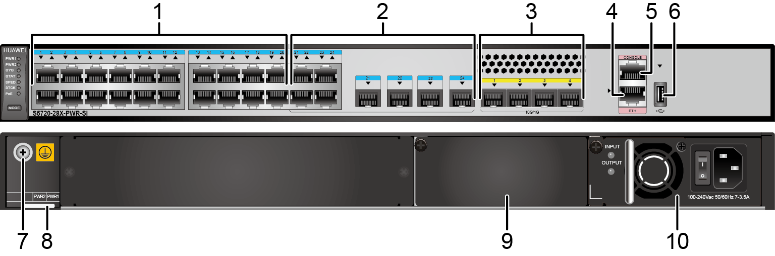
| 1 | Twenty PoE+ 10/100/1000BASE-T ports | 2 | Four combo ports (10/100/1000BASE-T (PoE+) + 100/1000BASE-X) Modules applicable to combo optical ports:
|
| 3 | Four 10GE SFP+ ports Applicable modules and cables:
NOTE:
If a port uses a GPON optical module, other 10GE SFP+ optical ports cannot be used. |
4 | One ETH management port |
| 5 | One console port NOTE:
It is used with a console cable. The console cable is not delivered with the switch and needs to be separately purchased if needed. |
6 | One USB port |
| 7 | Ground screw NOTE:
It is used with a ground cable. |
8 | ESN label NOTE:
You can draw it out to view the ESN and MAC address of the switch. |
| 9 | Power module slot 2 NOTE:
Applicable power modules:
|
10 | Power module slot 1 NOTE:
Applicable power modules:
|
Port Description
10/100/1000BASE-T port
By default, a combo port works in auto mode, in which the port type is determined as follows:
- If the optical port has no optical module installed and the electrical port has no Ethernet cable connected, the port type depends on which port is connected first. If the electrical port is connected by an Ethernet cable first, the electrical port is used for data switching. If the optical port has an optical module installed first, the optical port is used for data switching.
- If the electrical port has an Ethernet cable connected and is in Up state, the electrical port is still used for data switching when the optical port has an optical module installed.
- If the optical port, no matter in Up or Down state, has an optical module installed, the optical port is still used for data switching when the electrical port has an Ethernet cable connected.
- If the optical port has an optical module installed and the electrical port has an Ethernet cable connected, the optical port is used for data switching after the switch restarts.
USB flash drives from different vendors differ in model compatibility and drivers. If a USB flash drive cannot be used, try to replace it with another one from a mainstream vendor. Switches support a maximum of 128 GB USB flash drives.
Indicator Description
The S5720-28X-PWR-SI-AC has the same types of indicators as the S5720-52X-PWR-SI-AC. For details, see Indicator Description.Power Supply Configuration
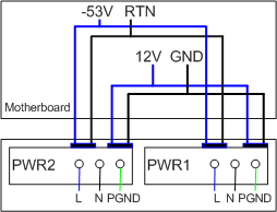
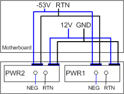
The S5720-28X-PWR-SI-AC is a PoE switch. It has two power module slots, each of which can have a 500 W or 650 W power module installed. A power module can provide 369.6 W of PoE power for powered devices (PDs). A 500 W AC power module and a 650 W DC power module can be used together in the switch. Table 6 lists its power supply configurations.
| Power Module 1 | Power Module 2 | Available PoE Power | Maximum Number of Ports (Fully Loaded) |
|---|---|---|---|
| 500 W or 650 W | - | 369.6 W |
|
| 500 W or 650 W | 500 W or 650 W | 739.2 W |
|
When a switch has two power modules installed, the two power modules work in redundancy mode to provide power for the chassis and in load balancing mode to provide power for PDs.
Heat Dissipation
The S5720-28X-PWR-SI-AC has a built-in fan for forced air cooling. Air flows in from the left side and front panel, and exhausts from the right side.
Technical Specifications
Table 7 lists technical specifications of the S5720-28X-PWR-SI-AC.
Item |
Description |
|---|---|
Memory (RAM) |
512 MB |
Flash |
512 MB in total. To view the available flash memory size, run the display version command. |
Mean time between failures (MTBF) |
66.78 years |
| Mean time to repair (MTTR) | 2 hours |
Availability |
> 0.99999 |
Service port surge protection |
Common mode: ±6 kV |
Power supply surge protection |
|
Dimensions (H x W x D) |
44.4 mm x 442.0 mm x 420.0 mm (1.75 in. x 17.4 in. x 16.5 in.) |
Weight (with packaging) |
9.3 kg (20.51 lb) |
Stack ports |
GE electrical ports and 10GE SFP+ optical ports except combo ports on the front panel |
RTC |
Supported |
RPS |
Not supported |
PoE |
Supported |
Rated voltage range |
100 V AC to 240 V AC, 50/60 Hz -48 V DC to -60 V DC |
Maximum voltage range |
90 V AC to 264 V AC, 47 Hz to 63 Hz -38.4 V DC to -72 V DC |
Maximum power consumption (100% throughput, full speed of fans) |
|
Typical power consumption (30% of traffic load)
|
31.8 W |
Operating temperature |
0°C to 45°C (32°F to 113°F) at an altitude of 0-1800 m (0-5906 ft.) NOTE:
When the altitude is 1800-5000 m (5906-16404 ft.), the highest operating temperature reduces by 1°C (1.8°F) every time the altitude increases by 220 m (722 ft.). |
Short-term operating temperature |
-5°C to +50°C (23°F to 122°F) at an altitude of 0-1800 m (0-5906 ft.) NOTE:
When the altitude is 1800-5000 m (5906-16404 ft.), the highest operating temperature reduces by 1°C (1.8°F) every time the altitude increases by 220 m (722 ft.). The equipment can operate beyond the normal operating
temperature range for a short-term period, but the following conditions
must be met:
The equipment cannot start when the temperature is lower than 0°C (32°F). The maximum distance of optical modules used in these conditions cannot exceed 10 km. |
Storage temperature |
-40°C to +70°C (-40°F to +158°F) |
Noise under normal temperature (27°C, sound power) |
< 56.5 dB(A) |
Relative humidity |
5% to 95%, noncondensing |
Operating altitude |
0-5000 m (0-16404 ft.) |
Certification |
|
Part number |
02350DLW |