S6730-H48X6C
Version Mapping
Table 1 lists the mapping between the S6730-H48X6C chassis and software versions.
Appearance and Structure
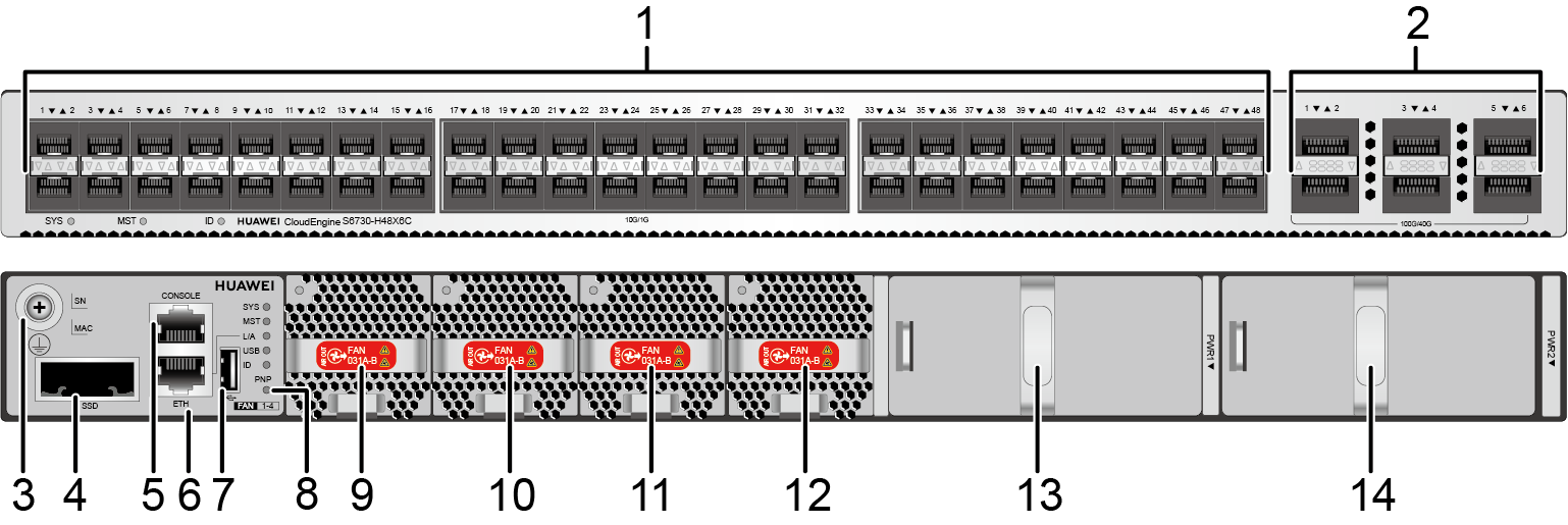
1 |
Forty-eight 10GE SFP+ ports Applicable modules and cables:
|
2 |
Six 40GE/100GE QSFP28 optical ports Applicable modules and cables:
NOTE:
A QSFP28 optical port cannot be split into four 10GE ports, regardless of whether the port uses a QSFP28 or QSFP+ optical module. By default, the S6730-H48X6C (part number: 02352FSF) does not have the license loaded, and QSFP28 ports on the switch are 40GE ports. The QSFP28 ports can work as 100GE ports after you activate the license, run the assign port-speed 100GE command, and restart the switch. On the S6730-H48X6C (part number: 02353FWL), the license has been activated and QSFP28 ports on these switches work as 100GE ports. To change the rate of QSFP28 ports from 100GE to 40GE, run the undo assign port-speed 100GE command and restart the switch. |
3 |
Ground screw NOTE:
It is used with a ground cable. |
4 |
SSD card slot NOTE:
This slot is reserved for future use. |
5 |
One console port |
6 |
One ETH management port |
7 |
One USB port |
8 |
One PNP button NOTICE:
To restore the factory settings and reset the switch, hold down the button for at least 6 seconds. To reset the switch, press the button. Resetting the switch will cause service interruption. Exercise caution when you press the PNP button. |
9 |
Fan module slot 1 NOTE:
Applicable fan module: FAN-031A-B Fan Module |
10 |
Fan module slot 2 NOTE:
Applicable fan module: FAN-031A-B Fan Module |
11 |
Fan module slot 3 NOTE:
Applicable fan module: FAN-031A-B Fan Module |
12 |
Fan module slot 4 NOTE:
Applicable fan module: FAN-031A-B Fan Module |
13 |
Power module slot 1 NOTE:
Applicable power module: |
14 |
Power module slot 2 NOTE:
Applicable power module: |
Port Description
10GE SFP+ optical port
40GE/100GE QSFP28 optical port
Console port
ETH management port
USB port

USB flash drives from different vendors differ in model compatibility and drivers. If a USB flash drive cannot be used, try to replace it with another one from a mainstream vendor. Switches support a maximum of 128 GB USB flash drives.
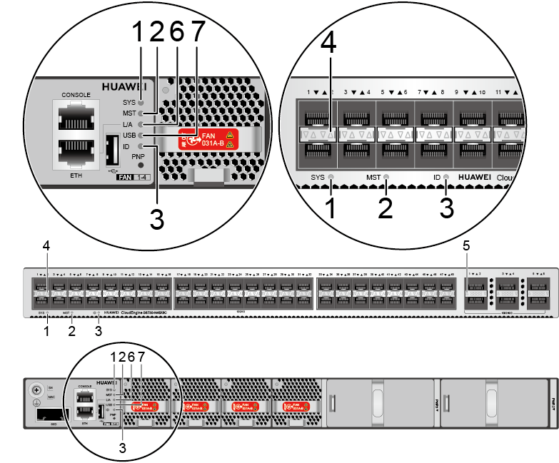
Indicator Description
No. |
Indicator |
Name |
Color |
Status |
Description |
|---|---|---|---|---|---|
1 |
SYS |
System status indicator |
- |
Off |
The system is not running. |
Green |
Fast blinking |
The system is starting. |
|||
Green |
Steady on |
During the system startup preparation phase, the SYS indicator is steady green, which lasts for a maximum of 30 seconds. |
|||
Green |
Slow blinking |
The system is running normally. |
|||
Red |
Steady on |
The system does not work normally after registration, or a fan alarm or a temperature alarm has been generated. |
|||
2 |
MST |
Stack indicator |
- |
Off |
The switch is not the master switch in a stack. |
Green |
Steady on |
The switch is the master switch in a stack or a standalone switch. |
|||
3 |
ID |
ID indicator |
- |
Off |
The ID indicator is not used (default state). |
Blue |
Steady on |
The indicator identifies the switch to maintain. The ID indicator can be turned on or off remotely to help field engineers find the switch to maintain. |
|||
4 |
- |
Service port indicator (10GE optical port) |
- |
Off |
The port is not connected or has been shut down. |
Green |
Steady on |
A link has been established on the port. |
|||
- |
Off |
The port is not sending or receiving data. |
|||
Yellow |
Blinking |
The port is sending or receiving data. |
|||
5 |
- |
Service port indicator (40GE/100GE optical port) |
- |
Off |
The port is not connected or has been shut down. |
Green |
Steady on |
A link has been established on the port. |
|||
Blinking |
The port is sending or receiving data. |
||||
6 |
L/A |
ETH port indicator |
- |
Off |
The ETH port is not connected. |
Green |
Steady on |
The ETH port is connected. |
|||
Green |
Blinking |
The Eth port is sending or receiving data. |
|||
7 |
USB |
USB-based deployment indicator |
- |
Off |
|
Green |
Steady on |
A USB-based deployment has been completed. |
|||
Green |
Blinking |
The system is reading data from a USB flash drive. |
|||
Yellow |
Steady on |
The switch has copied all the required files and completed the file check. The USB flash drive can be removed from the switch. |
|||
Red |
Blinking |
An error has occurred when the system is executing the configuration file or reading data from the USB flash drive. |
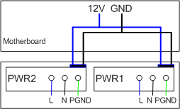
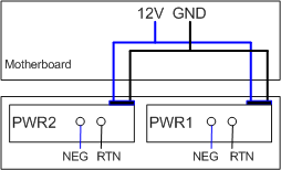
Power Supply Configuration
The S6730-H48X6C can use a single power module or double power modules for 1+1 power redundancy. Pluggable AC and DC power modules can be used together in the same switch.
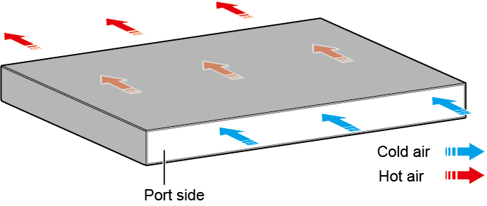
Heat Dissipation
The S6730-H48X6C uses pluggable fan modules for forced air cooling. Air flows in from the front side and exhausts from the rear panel. Fan modules support 3+1 backup.
Technical Specifications
Table 7 lists technical specifications of the S6730-H48X6C.
Item |
Description |
|---|---|
Memory (RAM) |
4 GB |
Flash |
2 GB in total. To view the available flash memory size, run the display version command. |
Mean time between failures (MTBF) |
56.87 years |
Mean time to repair (MTTR) |
2 hours |
Availability |
> 0.99999 |
Service port surge protection |
N/A |
Power supply surge protection |
|
Dimensions (H x W x D) |
|
Weight (with packaging) |
9.2 kg (20.28 lb) |
Stack ports |
|
RTC |
Supported |
RPS |
Not supported |
PoE |
Not supported |
Rated voltage range |
|
Maximum voltage range |
|
Maximum power consumption (100% throughput, full speed of fans) |
291 W |
Typical power consumption (30% of traffic load, tested according to ATIS standard) |
165 W |
Operating temperature |
-5°C to +45°C (23°F to 113°F) at an altitude of 0-1800 m (0-5906 ft.)
NOTE:
When the altitude is 1800-5000 m (5906-16404 ft.), the highest operating temperature reduces by 1°C (1.8°F) every time the altitude increases by 220 m (722 ft.). The switch cannot be started when the ambient temperature is lower than 0°C (32°F). |
Storage temperature |
-40°C to +70°C (-40°F to +158°F) |
Noise under normal temperature (27°C, sound power) |
< 65 dB(A) |
Relative humidity |
5% to 95%, noncondensing |
Operating altitude |
0-5000 m (0-16404 ft.) |
Certification |
|
Part number |
|