S6720-32C-SI-DC
Version Mapping
Table 1 lists the mapping between the S6720-32C-SI-DC and software versions.
Appearance and Structure
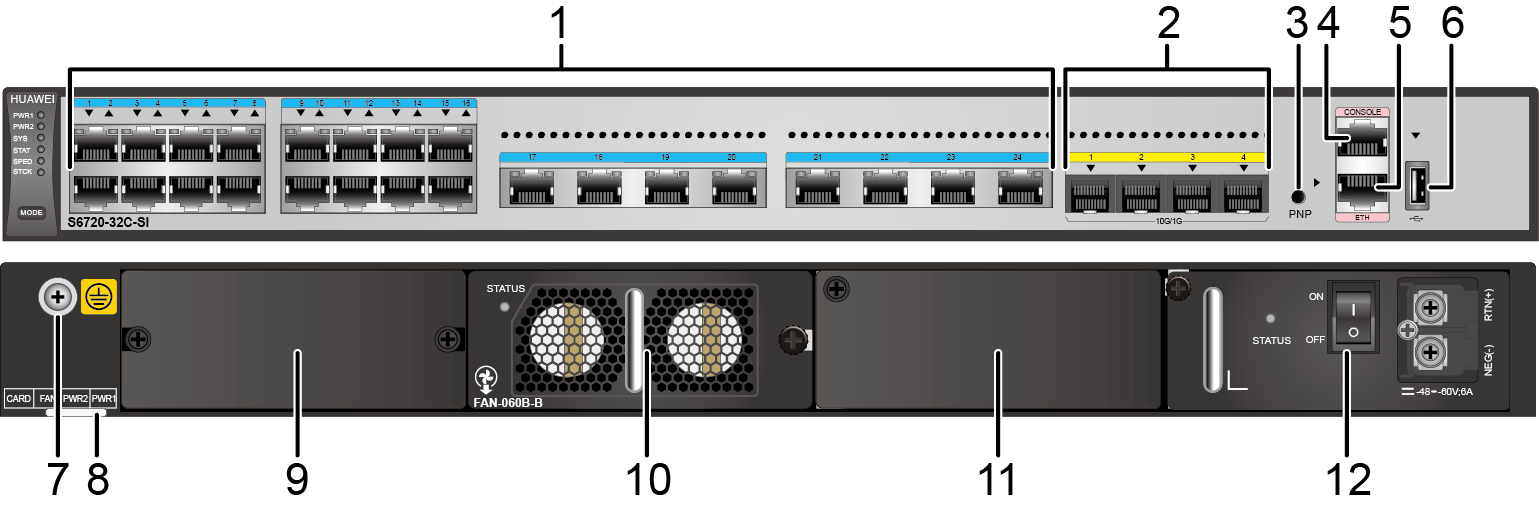
1 |
Twenty-four 100M/1000M/2.5GE/5GE/10GE BASE-T ports (MultiGE port) |
2 |
Four 10GE SFP+ ports Applicable modules and cables:
NOTE:
The four 10GE SFP+ ports on the front panel cannot be used simultaneously with ports on the rear card (except the 4-port 10GE rear card). If a rear card other than a 4-port 10GE rear card is installed in the switch, only the ports on the front panel can be used by default.
|
3 |
One PNP button NOTICE:
Applicable in V200R012C00 and later versions: To restore the factory settings and reset the switch, hold down the button for at least 6 seconds. To reset the switch, press the button. Resetting the switch will cause service interruption. Exercise caution when you press the PNP button. |
4 |
One console port |
5 |
One ETH management port |
6 |
One USB port |
7 |
Ground screw NOTE:
It is used with a ground cable. |
8 |
ESN label NOTE:
You can draw it out to view the ESN and MAC address of the switch. |
9 |
Rear card slot NOTE:
Cards supported:
|
10 |
Fan slot NOTE:
Applicable fan module: FAN-060B-B |
11 |
Power module slot 2 NOTE:
Applicable power modules:
|
12 |
Power module slot 1 NOTE:
Applicable power modules:
|
Port Description
100M/1000M/2.5GE/5GE/10GE BASE-T port (MultiGE port)
Cable Type (6-a-1 Bundle) |
MultiGE Port (Different Rates) |
|||
|---|---|---|---|---|
24*100M/1000M |
24x2.5GE |
24x5GE |
24x10GE |
|
Category 5e unshielded twisted pair (Cat5e UTP) |
100 m |
100 m |
Not recommended due to high risk |
Not supported |
Category 5e shielded twisted pair (Cat5e STP) |
100 m |
100 m |
100 m |
Not supported |
Category 6 unshielded twisted pair (Cat6 UTP) |
100 m |
100 m |
100 m Not recommended due to high risk |
Not supported |
Category 6 shielded twisted pair (Cat6 STP) |
100 m |
100 m |
100 m |
Not supported |
Category 6A unshielded twisted pair (Cat6A U/UTP) |
100 m |
100 m |
100 m Not recommended due to high risk |
Not supported |
Category 6A foiled/unshielded twisted pair (Cat6A F/UTP) |
100 m |
100 m |
100 m |
100 m |
Category 6A shielded twisted pair (Cat6A STP) |
100 m |
100 m |
100 m |
100 m |
Category 7 twisted pair (Cat7) |
100 m |
100 m |
100 m |
100 m |

6-a-1 stands for the six-around-one cable bundle mode, with one cable in the center and six cables bundled evenly around it.
- 802.3bz requires that the ALSNR value for alien crosstalk between Ethernet cables be greater than 0, but the standards for Cat5e and Cat6 unshielded twisted pairs do not specify the required ALSNR value. Therefore, such cables may not meet the crosstalk requirement in 802.3bz, causing severe problems such as continuous packet loss.
- According the cabling specification TIA TSB-5021, using Cat5e and Cat6 cables for 5G poses high risks.
- Currently, no clear onsite testing or evaluation method is available for checking whether ALSNR of cables conforms to 802.3bz.
If Cat5e and Cat6 unshielded twisted pairs do not meet the 5G requirement, you are advised to replace them with shielded twisted pairs or reduce the rate of interfaces to 2.5G.
10GE SFP+ port
Console port
ETH management port
USB port
USB flash drives from different vendors differ in model compatibility and drivers. If a USB flash drive cannot be used, try to replace it with another one from a mainstream vendor. Switches support a maximum of 128 GB USB flash drives.
Indicator Description
The S6720-32C-SI-DC has similar indicators to those of the S6720-32C-PWH-SI-AC, except that the S6720-32C-SI-DC does not have a PoE indicator. For details, see Indicator Description.
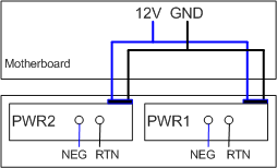
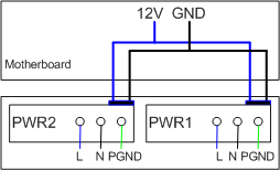
Power Supply Configuration
The S6720-32C-SI-DC uses pluggable power modules. It can be configured with a single power module or double power modules for 1+1 power redundancy. Pluggable AC and DC power modules can be used together in the same switch.
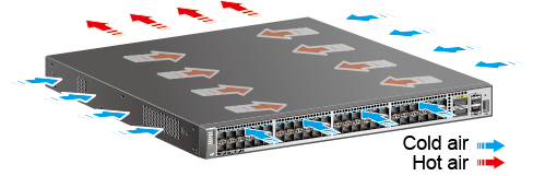
Heat Dissipation
The S6720-32C-SI-DC uses a pluggable fan module for forced air cooling. Air flows in from the left, right, and front sides, and exhausts from the rear panel.
Technical Specifications
Table 7 lists specifications of the S6720-32C-SI-DC.
Item |
Description |
|---|---|
Memory (RAM) |
1 GB |
Flash |
512 MB in total. To view the available flash memory size, run the display version command. |
Mean time between failures (MTBF) |
27.4 years |
Mean time to repair (MTTR) |
2 hours |
Availability |
> 0.99999 |
Service port surge protection |
Common mode: ±7 kV |
Power supply surge protection |
|
Dimensions (H x W x D) |
44.4 mm x 442.0 mm x 420.0 mm (1.75 in. x 17.4 in. x 16.5 in.) |
Weight (including package) |
8.7 kg (19.18 lb) |
Stack ports |
Any MultiGE, 10GE SFP+, or 40GE QSFP+ ports (a maximum of 16 physical ports) |
RTC |
Supported |
RPS |
Not supported |
PoE |
Not supported |
Rated voltage range |
100 V AC to 240 V AC, 50/60 Hz -48 V DC to -60 V DC |
Maximum voltage range |
90 V AC to 264 V AC, 47 Hz to 63 Hz -36 V DC to -72 V DC |
Maximum power consumption (100% throughput, full speed of fans) |
117.62 W (without card) |
Typical power consumption (30% of traffic load, tested according to ATIS standard) |
93 W (without card) |
Operating temperature |
0°C to 45°C (32°F to 113°F) at an altitude of 0-1800 m (0-5906 ft.) NOTE:
When the altitude is 1800-5000 m (5906-16404 ft.), the highest operating temperature reduces by 1°C (1.8°F) every time the altitude increases by 220 m (722 ft.). |
Short-term operating temperature |
-5°C to +50°C (23°F to 122°F) at an altitude of 0-1800 m (0-5906 ft.) NOTE:
When the altitude is 1800-5000 m (5906-16404 ft.), the highest operating temperature reduces by 1°C (1.8°F) every time the altitude increases by 220 m (722 ft.). The equipment can operate beyond the normal operating
temperature range for a short-term period, but the following conditions
must be met:
The equipment cannot start when the temperature is lower than 0°C (32°F). The maximum distance of optical modules used in these conditions cannot exceed 10 km. |
Storage temperature |
-40°C to +70°C (-40°F to +158°F) |
Noise under normal temperature (27°C, sound power) |
< 62.3 dB(A) |
Relative humidity |
5% to 95%, noncondensing |
Operating altitude |
|
Certification |
|
Part number |
98010716 |