S6720-50L-HI-48S
Version Mapping
Table 1 lists the mapping between the S6720-50L-HI-48S chassis and software versions.
Appearance and Structure
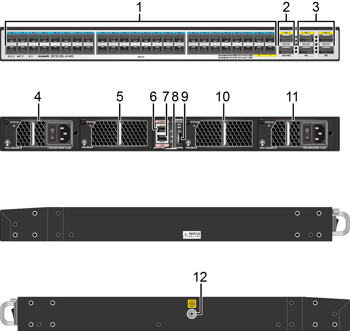
| 1 | Forty-eight 10GE SFP+ ports Applicable
modules and cables:
|
2 | Two 40GE/100GE QSFP28 ports Applicable
modules and cables:
NOTE:
A QSFP28 optical port cannot be split into four 10GE ports. The default rate is 40 Gbit/s, and you can run the set device port-config-mode 100g-port enable command to change the rate to 100 Gbit/s. When you run the command on either of the ports, both ports are configured to work at the rate of 100 Gbit/s simultaneously. After the rate is changed from 40 Gbit/s to 100 Gbit/s, ports 10GE0/0/45 to 10GE0/0/48 become unavailable. |
| 3 | Four 40GE QSFP+ ports Applicable
modules and cables:
NOTE:
A 40GE QSFP+ optical port cannot
be split into four 10GE ports. |
4 | Power module slot 1 NOTE:
Applicable power modules:
|
| 5 | Fan slot 1 NOTE:
Applicable fan module: FAN-40HA-B Fan Module |
6 | One console port |
| 7 | One ETH management port | 8 | ESN label NOTE:
You can draw it out to view the ESN and MAC address of the switch. |
| 9 | One USB port | 10 | Fan slot 2 NOTE:
Applicable fan module: FAN-40HA-B Fan Module |
| 11 | Power module slot 2 NOTE:
Applicable power modules:
|
12 | Ground screw NOTE:
It is used with a ground cable. |
Port Description
10GE SFP+ port
Indicator Description
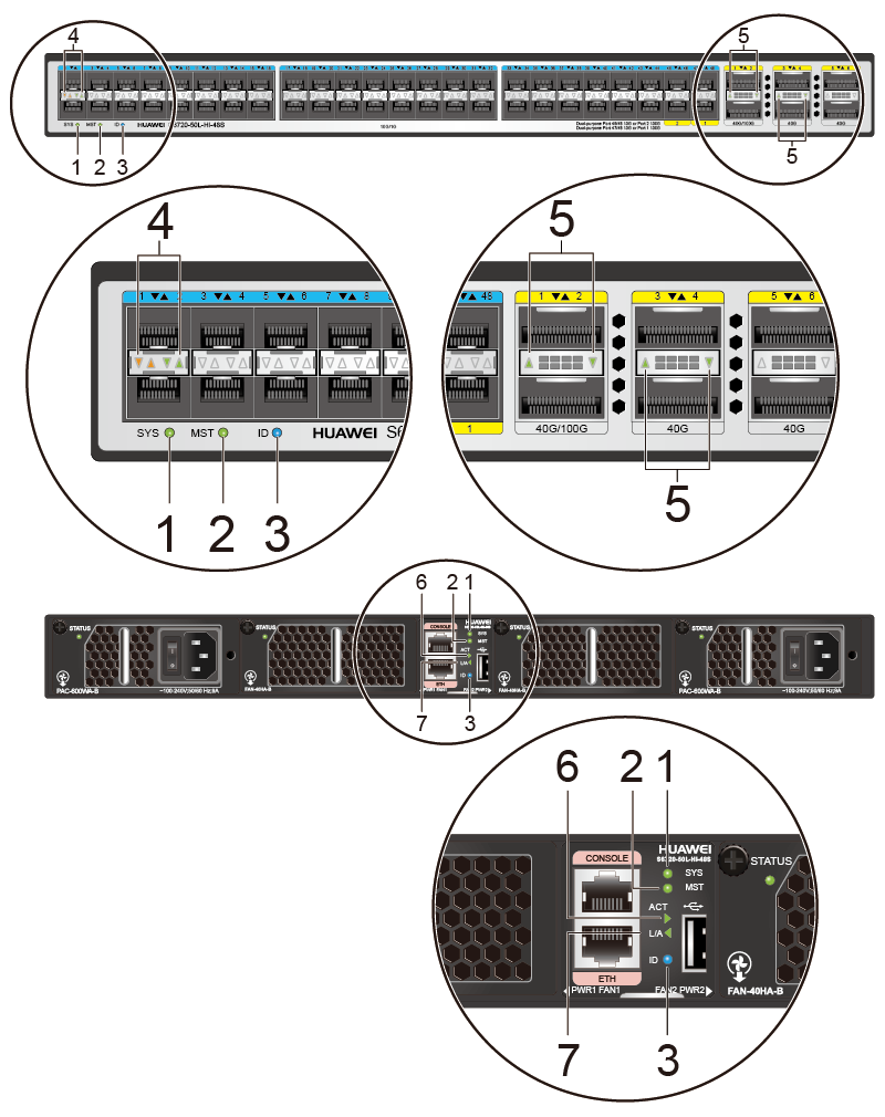
| No. | Indicator | Name | Color | Status | Description |
|---|---|---|---|---|---|
| 1 | SYS | System status indicator | - | Off | The system is not running. |
| Green | Fast blinking | The system is starting. | |||
| Green | Steady on | In the system startup preparation phase, the SYS indicator is steady green for no more than 15 seconds. | |||
| Green | Slow blinking | The system is running normally. | |||
| Red | Steady on | The system does not work normally after registration, or a fan alarm or temperature alarm has been generated. | |||
| 2 | MST | stack indicator | - | Off | The switch is not a stack master. |
| Green | Steady on | The switch is a stack master or standalone switch. | |||
| 3 | ID | ID indicator | - | Off | The ID indicator is not used (default state). |
| Blue | Steady on | The indicator identifies the switch to maintain. The ID indicator can be turned on or off remotely to help field engineers find the switch to maintain. | |||
| 4 | - | Service port indicator (10GE optical port) |
- | Off | The port is not connected or has been shut down. |
| Green | Steady on | The port is connected. | |||
| - | Off | The port is not sending or receiving data. | |||
| Yellow | Blinking | The port is sending or receiving data. | |||
| 5 | - | Service port indicator (40GE or 40GE/100GE optical port) |
- | Off | The port is not connected or has been shut down. |
| Green | Steady on | The port is connected. | |||
| Green | Blinking | The port is sending or receiving data. | |||
| 6 | ACT | USB-based deployment indicator | - | Off |
|
| Green | Steady on | A USB-based deployment has been completed. | |||
| Green | Blinking | The system is reading data from the USB flash drive. | |||
| Yellow | Steady on | The switch has copied all the required files and completed the file check. The USB flash drive can be removed from the switch. | |||
| Red | Blinking | An error has occurred when the system is executing the configuration file or reading data from the USB flash drive. | |||
| 7 | L/A | ETH port indicator | - | Off | The ETH port is not connected. |
| Green | Steady on | The ETH port is connected. | |||
| Green | Blinking | The ETH port is sending or receiving data. |
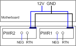
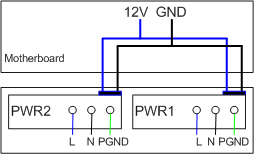
Power Supply Configuration
The S6720-50L-HI-48S uses pluggable power modules. It can be configured with a single power module or double power modules for 1+1 power redundancy. Pluggable AC and DC power modules can be used together in the same switch.
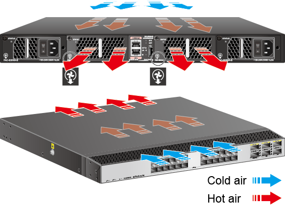
Heat Dissipation
The S6720-50L-HI-48S uses pluggable fan modules for forced air cooling. The airflow direction is front-to-rear.
Technical Specifications
Table 8 lists technical specifications of the S6720-50L-HI-48S.
Item |
Description |
|---|---|
Memory (RAM) |
2 GB |
Flash |
1 GB in total. To view the available flash memory size, run the display version command. |
Mean time between failures (MTBF) |
54.65 years |
| Mean time to repair (MTTR) | 2 hours |
Availability |
> 0.99999 |
Service port surge protection |
NA |
Power supply surge protection |
|
Dimensions (H x W x D) |
43.6 mm x 442.0 mm x 420.0 mm (1.72 in. x 17.4 in. x 16.5 in.) |
Weight (with packaging) |
10.2 kg (22.49 lb) |
Stack ports |
|
RTC |
Supported |
RPS |
Not supported |
PoE |
Not supported |
Rated voltage range |
100 V AC to 240 V AC, 50/60 Hz -48 V DC to -60 V DC |
Maximum voltage range |
90 V AC to 264 V AC, 47 Hz to 63 Hz -38.4 V DC to -72 V DC |
Maximum power consumption (100% throughput, full speed of fans) |
279 W |
Typical power consumption (30% of traffic load, tested according to ATIS standard) |
194 W |
Operating temperature |
0°C to 45°C (32°F to 113°F) at an altitude of 0-1800 m (0-5906 ft.) NOTE:
When the altitude is 1800-5000 m (5906-16404
ft.), the highest operating temperature reduces by 1°C (1.8°F) every
time the altitude increases by 220 m (722 ft.). |
Storage temperature |
-40°C to +70°C (-40°F to +158°F) |
Noise under normal temperature (27°C, sound power) |
< 65 dB(A) |
Relative humidity |
5% to 95%, noncondensing |
Operating altitude |
0-5000 m (0-16404 ft.) |
Certification |
|
| Part number | 02351MXN |